

- #BLENDER CADTOOLS HOW TO#
- #BLENDER CADTOOLS INSTALL#
- #BLENDER CADTOOLS SERIES#
- #BLENDER CADTOOLS DOWNLOAD#

I have used dictionaries in the past to store history and then give the use the ability to scroll back though them. This is something I will have to spend a lot of time researching I think…
#BLENDER CADTOOLS HOW TO#
I have absolutely no idea whatsoever how to do this! I took me ages to work out how to draw the Pivot Point so it responded dynamically to changes in the Location input boxes. It would need prediction and contextual algorithms with respect to the last actions performed. The idea is very basic (I’m thinking about it at the moment and trying to imagine how it could work), and probably not entirely understandable, but I hope it gives an idea. I know I know it would be a good challenge to do something like this, and it would probably be necessary that the tool has a sort of database that remembers the history of all the actions and the parameters modified for each single vertex, as well as a system that recognizes, for example, a rotation with respect to another vertex or object, or a displacement of a vertex in an absolute way instead of delta, etc … etc etc … The thing that I imagine, seeing your precision gui … is that it would be nice to have a sort of double way of drawing …ĭirectly on the 3D view, by dragging the cursor and the objects to be drawn, and inserting parameters through the gui, but with the condition that both modes are correlated, interact interactively, so as to be able to draw in an approximate way an element on the 3d view and then go to adjust the modified parameter in precision … I have just put it back as it was by using reciprocal values in the scale boxes (type 1/ in front of what was there): Moving the pivot point does not move the geometry, there are also so many ways to do this in Blender & PDT already. You can also put the Pivot Point at the cursor location, there are so many ways to set cursor location, I thought this was the best method to place it other than by scrubbing the location boxes, or inputing values for X, Y & Z, which you can also do of course. The size of the pivot point is determined by the Size value, e.g. The pivot point can be dislayed by clicking the PDT Pivot button, ESC removes it. It can also be used to scale the geometry by three factors about itself. This can be used to rotate the selected geometry, in the view plane about an axis normal to your screen, by the specified Angle amount. Here we have the Pivot Point shown as the axis drawn in red, green and blue.

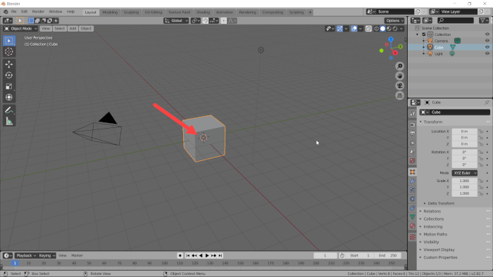
I started with a cube and scaled it as shown
#BLENDER CADTOOLS DOWNLOAD#
First download the last version from here or directly through this link: PROCAD26.zip.There is also a Wiki that can give you some information or my English replacement for original Italian UI updated at 2.60 the last version, see below.Īnyway if you use the Blender 2.49b like I suggested in the previous article ( Import DXF into Blender & fast settings), you can use this fantastic script and facilitate your drawings.
#BLENDER CADTOOLS SERIES#
The author posted a video about the improvements of a new version compatible for Blender 2.5x series but he has never updated his site since March 20, 2010. PROCAD written by Paolo Provenda (alias JAPY) is a Python script that implements in Blender (only 2.4x old series) some CAD tools using an handy GUI.
#BLENDER CADTOOLS INSTALL#
Let's see how install it and translate the UI in English. Fortunately there is PROCAD that helps the users to fix some aspects of own imported sketch. Where is the offset? How can I put the quotas? And so on. After importing DXF in Blender, some problems start immediately because the common commands present in any CAD don't exist in Blender, or simply aren't so simply to use as in the classical drawing software.


 0 kommentar(er)
